
Arduino M0 PRO: interrupt driven serial interface
SERCOM (SERial COMmunication interface) is the serial communication peripheral of the SAMD21. The SAMD21G18A has six peripheral instances (from SERCOM0 to SERCOM5) which can be configured to support USART, SPI o I2C mode. Signals from the SERCOM peripheral use four internal pads (from PAD0 to PAD3) which can be assigned to different GPIO pins. Peripheral serial mode can be chosen writing the field MODE[2:0] of CTRLA register:
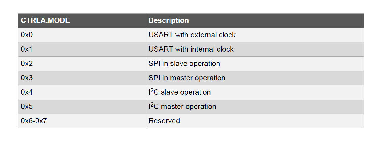
figure 1: operational modes of SERCOM serial communication peripheral
The peripheral can be configured in USART (Universal Synchronous and Asynchronous Receiver and Transmitter ) mode. The baud rate generator internal module uses an intenal generic clock (asynchronous) from Generic Clock Generator GCLK or an external clock (XCK). SERCOM has a single transmit buffer and a double receive buffer. I/O pins can be assigned to peripheral pads confiiguring the PORT controller writing PINMUXn registers (n = 0, … ,15) and choosing the specific SERCOM instance pads as alternative function for the pins. RXPO[1:0] (receive data pinout) and TXPO[1:0] (transmit data pinout) fields of CTRLA register specify which of the four internal SERCOM pads associate with RX, TX lines and, if need be, the external clock signal and hardware flow control signals CTS/RTS:
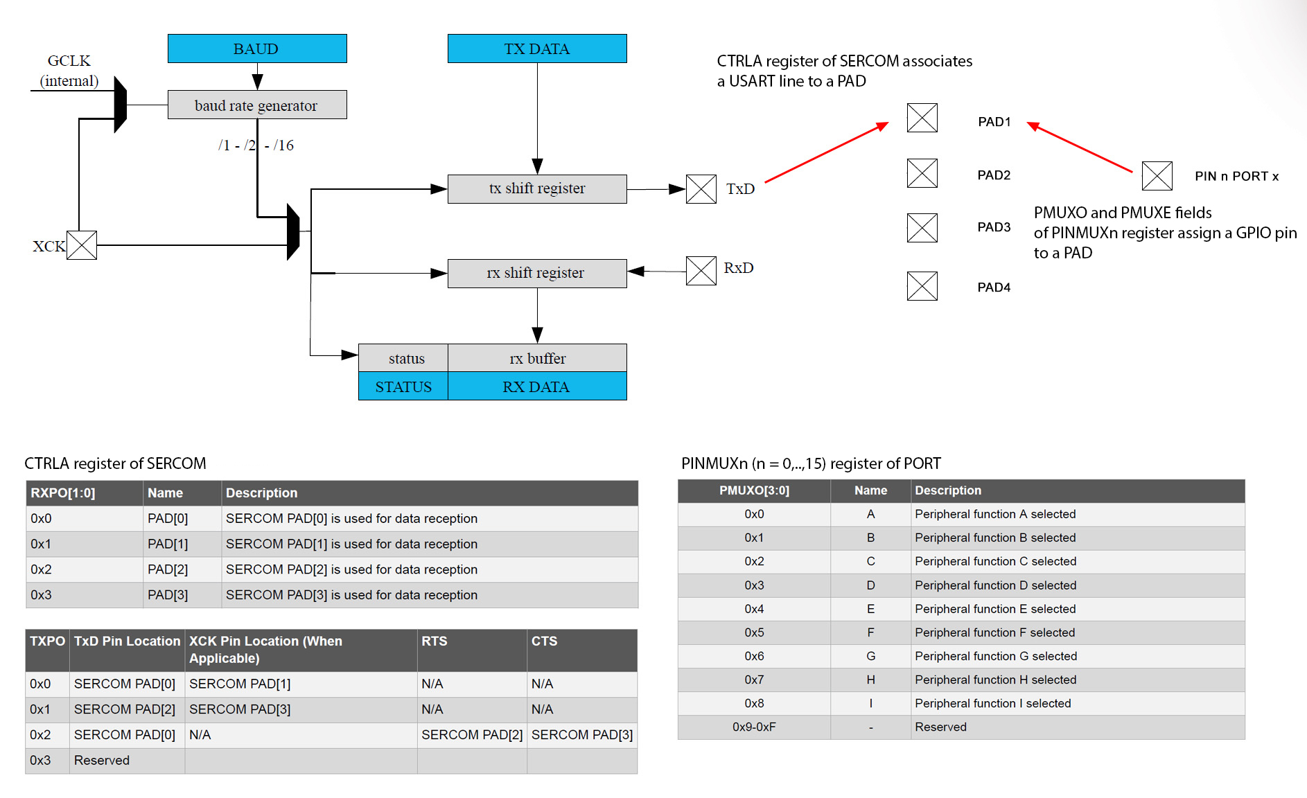
figure 2: SERCOM-USART pin multiplexing
To assign GPIO pins to the internal SERCOM pads we must configure PINCFGn (n = 0, … , 31) and PINMUXn (n = 0 , … , 15) of PORT peripheral. PINCFGn.PMUXEN enables alternaltive functions on the specific pin (n goes from 0 a 31, one register for each pin in the group) whereas PINMUXn.PMUXE e PINMUXn.PMUXO are two 4-bit fields (PINMUXn, with from 0 to 15 are 8-bit registers) are used to select alternative function for the even and odd pins respectively: n * 2 equals the even pin to be configured, n * 2 + 1 the odd one (for example PINMUX11 lets us select alternaltive function for pins 22 and 23 of the group):
void port_init(void)
{
  /* assign alternate function (SERCOM5 PAD2 and PAD3) to pin PB22 and PB23 */
  PORT->Group[1].PINCFG[22].bit.PMUXEN = 1;  // enable alternate function on pin PB22
  PORT->Group[1].PINCFG[23].bit.PMUXEN = 1;  // enable alternate function on pin PB23
  PORT->Group[1].PMUX[11].bit.PMUXE = 0x03;  // pin PB22 is assigned to SERCOM5 PAD2
  PORT->Group[1].PMUX[11].bit.PMUXO = 0x03;  // pin PB23 is assigned to SERCOM5 PAD3
}
Pin PB22 and PB23 are linked to Embedded Debugger EDBG on the Arduino M0 PRO board and works as USB-serial converter. THese two pins can be assigned to PAD2 (PB22) and PAD3 (PB23) of SERCOM5 serial instance (lternative function D, the complete alternative pin function mapping is on the mcu datasheet under I/O Multiplexing). We can plug a USB cable into programming USB port of Arduino M0 PRO and open a serial terminal like Putty to communciate with the SAMD21 serial. Once GPIO pins are assigned to SERCOM5 PAD2 and PAD3we need to route USART RX and TX signals to the pads:
void USART_init(void)
{
  SERCOM5->USART.CTRLA.bit.RXPO = 0x3;    // RX on PAD3
  SERCOM5->USART.CTRLA.bit.TXPO = 0x1;    // TX on PAD2
}
CTRLA and CTRLB registers are used to configure and enable USART:
- CTRLA.MODE is programmed with the serial mode (USART, SPI or I2C)
- CTRLA.CMODE selects synchronous or asynchronous communication
- CTRLA.RXPO and CTRLA.TXPO select the pads for RX and TX lines
- data order, most significant bit first (MSB) or least significant bit first (LSB), is specified in CTRLA.DORD
- number of frame data bits is programmed into CTRLB.CHSIZE
- parity check is enabled in CTRLA.FORM and configured as odd or even parity, in CTRLB.FORM
- CTRLB.SBMODE specifies the number of stop bits
- baud rate is programmed into BAUD register
- RX and TX lines are enabled in CTRLB.RXEN e CTRLB.TXEN
- CTRLA.ENABLE enables USART
Here I configure SERCOM5 instance as asynchronous USART (UART), 8-bit data frame, no parity, one stop bit and a 115200 bps baud rate (8N1):
void USART_init(void)
{
  // configure USART 8N1
  SERCOM5->USART.CTRLA.bit.MODE = 0x1;    // USART internal clock
  SERCOM5->USART.CTRLA.bit.CMODE = 0;     // asynchronous mode
  SERCOM5->USART.CTRLA.bit.RXPO = 0x3;    // RX on PAD3
  SERCOM5->USART.CTRLA.bit.TXPO = 0x1;    // TX on PAD2
  SERCOM5->USART.CTRLA.bit.DORD = 1;      // data order: LSB first
  SERCOM5->USART.CTRLB.bit.CHSIZE = 0x0;  // 8-bit character
  SERCOM5->USART.CTRLA.bit.FORM = 0;      // no parity bit
  SERCOM5->USART.CTRLB.bit.SBMODE = 0;    // 1 stop bit
  SERCOM5->USART.BAUD.reg = 50437;        // 115200 baud rate
  SERCOM5->USART.CTRLB.bit.RXEN = 1;      // enable receiver
  SERCOM5->USART.CTRLB.bit.TXEN = 1;      // enable transmitter
  SERCOM5->USART.CTRLA.reg |= 1 << SERCOM_USART_CTRLA_ENABLE_Pos;    // enable USART
}
Peripheral synchronous clock must be enabled to write configuration registers (as explained in this post about SAMD21 clock distribution tree):
void clock_init(void)
{
  SYSCTRL->OSC8M.bit.PRESC = 0;                          // no prescaler (is 8 on reset)
  SYSCTRL->OSC8M.reg |= 1 << SYSCTRL_OSC8M_ENABLE_Pos;   // enable source

  GCLK->GENDIV.bit.ID = 0x03;                            // select GCLK_GEN[3]
  GCLK->GENDIV.bit.DIV = 0;                              // no prescaler

  GCLK->GENCTRL.bit.ID = 0x03;                           // select GCLK_GEN[3]
  GCLK->GENCTRL.reg |= GCLK_GENCTRL_SRC_OSC8M;           // OSC8M source
  GCLK->GENCTRL.bit.GENEN = 1;                           // enable generator

  GCLK->CLKCTRL.reg = GCLK_CLKCTRL_ID_SERCOM5_CORE;      // SERCOM5 multiplexer GCLK_PERIPHERAL[n]
  GCLK->CLKCTRL.reg |= GCLK_CLKCTRL_GEN_GCLK3;           // select multiplexer source GCLK_GEN[3]
  GCLK->CLKCTRL.bit.CLKEN = 1;                           // enable generic clock (for baud rate generation)

  PM->APBCSEL.bit.APBCDIV = 0;                           // no prescaler
  PM->APBCMASK.bit.SERCOM5_ = 1;                         // enable SERCOM5 synchronous clock
}
Once the serial is set up, we can write a simple application that receives and echoes back a message:
int main(void)
{
	clock_init();  // initialize system and peripheral clocks
	port_init();   // configure serial GPIO pins
	USART_init();  // configure and enable USART

	USART_write_wait("hello from SAMD21!\r\n");

	char buf[100];  // 100 characters buffer (don't exceed)

	while (1)
	{
		USART_read_wait(buf);
		USART_write_wait("received: ");
		USART_writeln_wait(buf);
	}
}
USART_write_wait() writes a null-terminated character string on the serial while USART_read_wait() waits for a character string terminated by the ‘\n’ line feed character and stores it in a local buffer. USART_writeln_wait() appends a line teminator character to the string. All these functions use USART_send_wait() and USART_receive_wait() to send and receive single characters:
void USART_send_wait(char data)
{
  while (!SERCOM5->USART.INTFLAG.bit.DRE)       // wait for the transmit buffer to be empty
    ;
  SERCOM5->USART.DATA.reg = data;
}

char USART_receive_wait(void)
{
  while (!SERCOM5->USART.INTFLAG.bit.RXC)       // wait for a character in the receive buffer
    ;
  return SERCOM5->USART.DATA.reg;
}

void USART_write_wait(const char *string)
{
  while (*string)
    USART_send(*string++);
}
void USART_writeln_wait(const char *string)
{
  USART_write(string);
  USART_write("\r\n");
}

void USART_read_wait(char *string)
{
  while ((*string = USART_receive()) != '\n')
    string++;
  *string = '\0';
}
These low level functions receive or transmit a single character at a time, polling the transmit and receive data registers status flags. Reading DATA register access the receive buffer and writing DATA register access the transmission buffer. INTFLAG Interrupt FLAG Status and Clear register contains a few bits (flags) that indicates the status of the peripheral:
- RXC – Receive Complete: is 1 when the reception data buffer contains at least one frame to be read, becomes 0 when all frames in the buffer has been read
- DRE – Data Register Empty: vis 1 when transmission data register is empty, 0 when the application writes data into the DATA register and the hardware loads the frame into the transmission buffer
- TXC – Transmit Complete: is 1 when the transmission buffer is empty and the shift register has done sending all the characters on the TX line, 0 when a frame is written into the transmission buffer
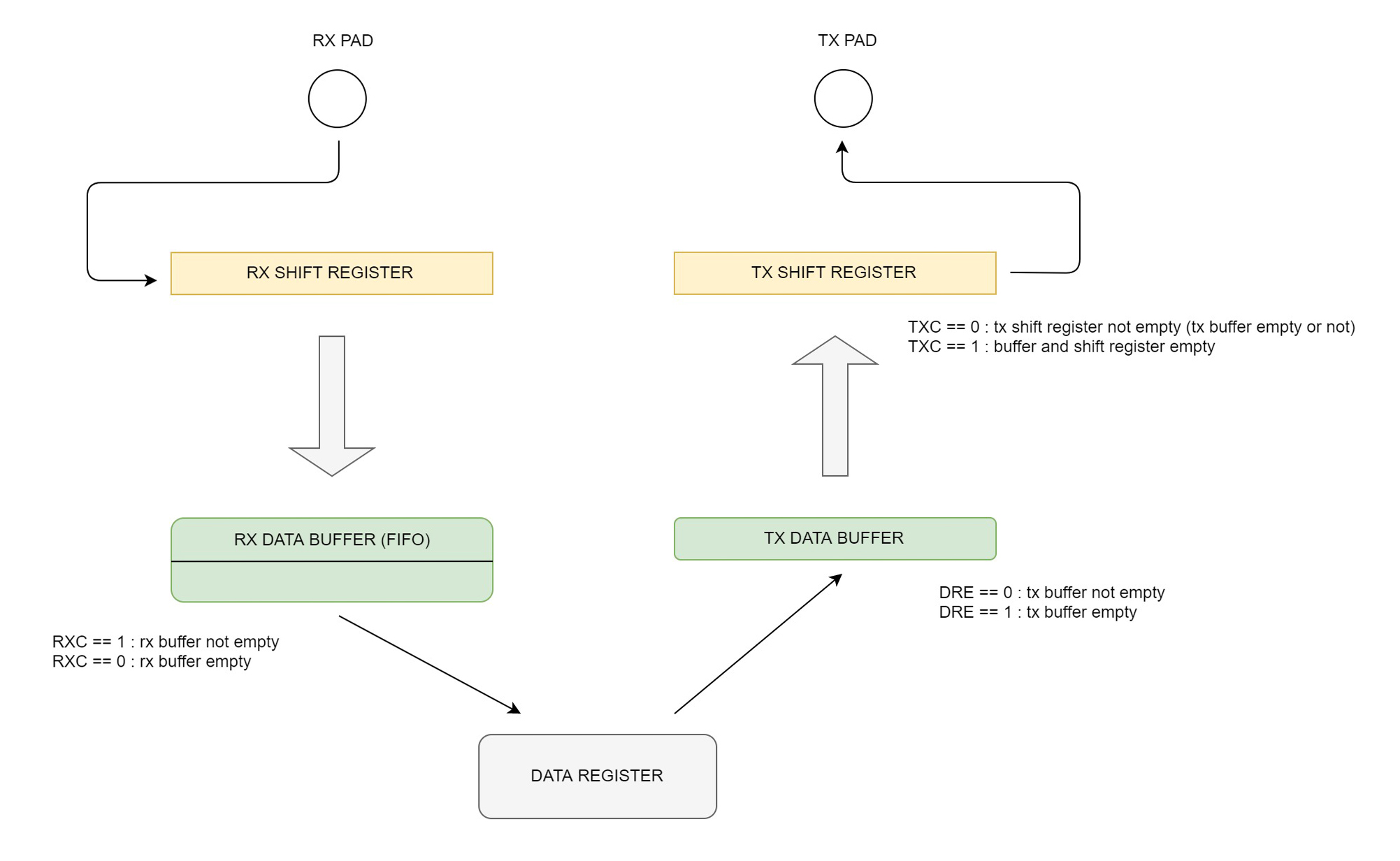
figure 3: SERCOM DATA register access transmission buffer when writing and receive buffer when reading. The INTFLAG register holds the status flagsThe code polls the flags into INTFLAG register, waiting for them to be set/cleared in order to perform the specific operation. Polling flags is not the beast nor the most efficient approach to I/O since it wastes CPU cycles in a busy wait (or gadfly loop as someone says), leaving no room for the processor to do anything else. A far better approach is to use interrupts.
NVIC: Nested Vectored Interrupt Controller
The NVIC or Nested Vectored Interrupt Controller is a core peripheral (meaning it is present in all processors of Cortex-M series) that is in charge of interupt management.The file core_cm0plus.h defines a structure that contains the register set for the NVIC:
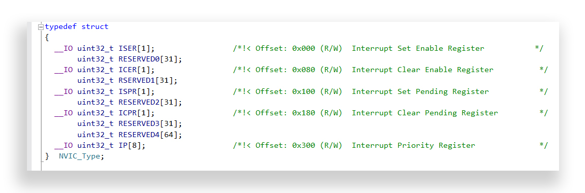
figure 4: C struct holding the register set for NVIC
This file defines some NVIC access functions as well; these functions use IRQn_Type, an enumerated data type defined in samd21g18a.h, which defines enumerators whose values corresponds to the system exceptions and IRQ requests from the various peripherals:
- void NVIC_EnableIRQ(IRQn_Type IRQn): enables interrupt (system exceptions are not supported);
- void NVIC_DisableIRQ(IRQn_Type IRQn): disables interrupt (system exceptions are not supported);
- void NVIC_SetPriority(IRQn_Type IRQn, uint32_t priority): sets the priority level for the interrupt or programmable system exception; Cortex-M0+ implements 4 priority levels from 0 to 3, with 0 being the highest priority level;
- uint32_t NVIC_GetPriority(IRQn_Type IRQn): returns the interrupt or system exception priority level;
- void NVIC_SetPendingIRQ(IRQn_Type IRQn): set the pending status for the interrupt; this function allows to trigger an interrupt via software (system exceptions are not supported);
- void NVIC_ClearPendingIRQ(IRQn_Type IRQn): clears the interrupt pending status (system exceptions are not supported);
- uint32 NVIC_GetPendingIRQ(IRQn_Type IRQn): returns the pending status of the interrupt (system exceptions are not supported);
System exceptions are numbered from 1 to 15; exceptions numbered from 16 are peripheral interrupts (interrupts are considered a particular type of exceptions). The NVIC of Cortex-M0+ implements up to 32 IRQs (Interrupt Requests), but only 28 are used in the SAMD21G18A. In the IRQn_Type enum system exceptions are numbered from -15 to -1 (system exception 0 is the reset vector), interrupts are numbered from 0 to 27:
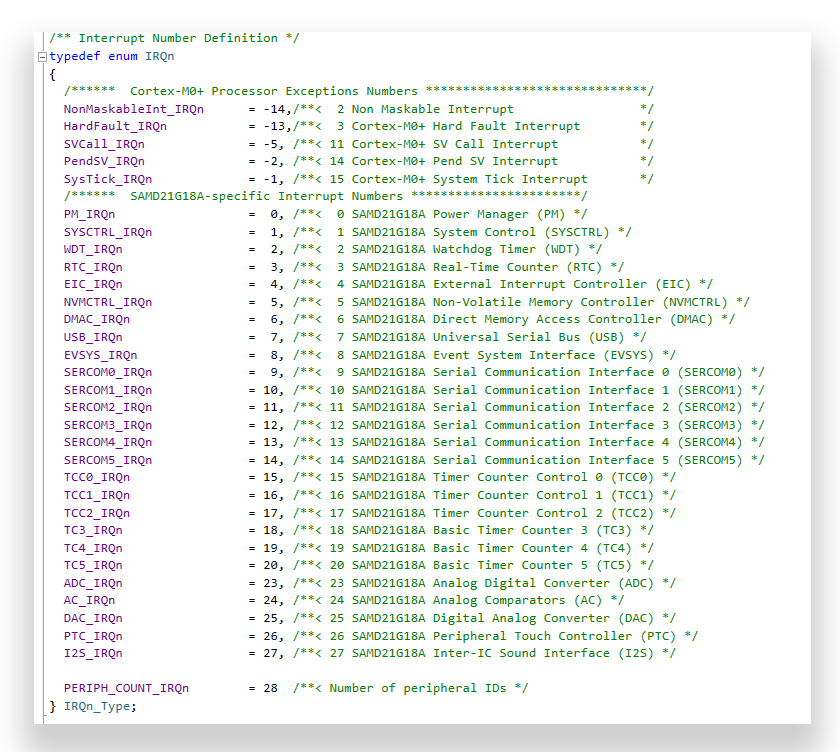
Figura 5: l’enumerazione IRQn_Type definita nel file samd21g18a.h e utilizzata nelle funzioni di accesso del NVIC
Each peripheral instance hai its personal interrupt line; the INTFLAG register holds status flags and each one of them triggers an interrupt. Since a SERCOM intance has a sningle interrupt line connected to the NVIC, all flags are OR-ed toghether and trigger the same IRQ; code inside the handler function or ISR (Interupt Service Routine) must examine the flags in order to determine which event triggered the requets. INTENSET e INTENCLR registers are used to enable and disable the peripheral interrupt (the interrupt must be enabled in the NVIC as well in order to be serviced):
void NVIC_init(void)
{
  NVIC_EnableIRQ(SERCOM5_IRQn);       // enable SERCOM0 interrupt request
  NVIC_SetPriority(SERCOM5_IRQn,0);   // highest priority
}

void USART_init(void)
{
  /* USART configuration code */
  .....
  .....
  SERCOM5->USART.INTENSET.bit.RXC = 1;   // enable receive complete interrupt
  SERCOM5->USART.INTENSET.bit.DRE = 1;   // enable data register empty interrupt
}
decoupling application from serial using FIFO circular buffers
In order for the CPU to process instructions while characters are received on the serial without the risk of losing data, software buffers are used, generally FIFO queues also called ring buffers or circular arrays The application no longer writes on the serial but sends data to a transmission buffer (TX buffer in figure 6) and the peripheral fetches characters from the buffer when ready. USART_write() stores characters into the buffers and returns. Similarly the application doesn’t poll for data but it’s up to the peripheral to store characters into the receive buffer (RX buffer in figure 6) and the application reads the data when needed:
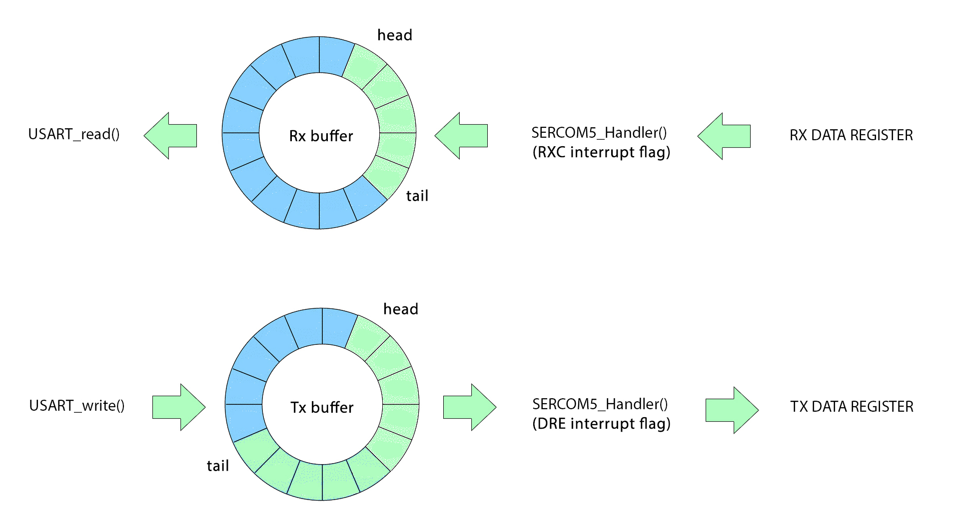
figure 6: circular FIFO buffers decouples application and serial communication
The size of the buffers are chosen based on the applciation at hand (how many characters must be sent/received and how often). The following code offers a simple implementation of a FIFO buffer; in this example buffers are implemented as two static arrays (but they could be dynamically allocated arrays or linked structures) and the array bounds are chosen at compile time defining the SIZE macro:
#define SIZE 100

 static char tx_buffer[SIZE], rx_buffer[SIZE];
 static int tx_head, rx_head;
 static int tx_tail, rx_tail;

 void FIFO_init(void)
 {
  tx_head = tx_tail = 0;
  rx_head = rx_tail = 0;
 }

 int TX_FIFO_is_empty(void)
 {
  return tx_tail == tx_head;
 }

 int TX_FIFO_is_full(void)
 {
  return (tx_tail + 1) % SIZE == tx_head;
 }

 int TX_FIFO_put(char data)
 {
  if (TX_FIFO_is_full())
    return 0;
  tx_buffer[tx_tail] = data;
  tx_tail = (tx_tail + 1) % SIZE;
  return 1;
 }

 int TX_FIFO_get(char *data)
 {
  if (TX_FIFO_is_empty())
    return 0;
  *data = tx_buffer[tx_head];
  tx_head = (tx_head + 1) % SIZE;
  return 1;
 }

 int RX_FIFO_is_empty(void)
 {
   return rx_tail == rx_head;
 }

 int RX_FIFO_is_full(void)
 {
   return (rx_tail + 1) % SIZE == rx_head;
 }

 int RX_FIFO_put(char data)
 {
   if (RX_FIFO_is_full())
     return 0;
   rx_buffer[rx_tail] = data;
   rx_tail = (rx_tail + 1) % SIZE;
   return 1;
 }

 int RX_FIFO_get(char *data)
 {
   if (RX_FIFO_is_empty())
     return 0;
   *data = rx_buffer[rx_head];
   rx_head = (rx_head + 1) % SIZE;
   return 1;
 }
FIFO_put() and FIFO_get() returns an integer that signals the success or failure of the operation. Functions that write or read data don’t interface with the peripheral registers but with the software FIFO module:
void USART_send(char data)
{
	while (!TX_FIFO_put(data))
		;
	if (!(SERCOM5->USART.INTENSET.reg & SERCOM_USART_INTENSET_DRE))     // data put in tx buffer: re-enable DRE interrupt if disabled
		SERCOM5->USART.INTENSET.reg = SERCOM_USART_INTENSET_DRE;
}

char USART_receive(void)
{
  char data;
  while (!RX_FIFO_get(&data))
    ;
  if (!(SERCOM5->USART.INTENSET.reg & SERCOM_USART_INTENSET_RXC))     // data received from rx buffer: re-enable RXC interrupt if disabled
    SERCOM5->USART.INTENSET.reg = SERCOM_USART_INTENSET_RXC;
  return data;
}

void USART_write(const char *string)
{
  while (*string)
    USART_send(*string++);
}

void USART_writeln(const char *string)
{
  USART_write(string);
  USART_write("\r\n");
}

void USART_read(char *string)
{
  while ((*string = USART_receive()) != '\n')
    string++;
  *string = '\0';
}

void SERCOM5_Handler(void)
{
  char data;
  if (SERCOM5->USART.INTFLAG.reg & SERCOM_USART_INTFLAG_DRE && SERCOM5->USART.INTENSET.reg & SERCOM_USART_INTENSET_DRE)  // if interrupt flag is set AND interrupt is enabled
  {
    if (!TX_FIFO_get(&data))   // if tx buffer is empty disable DRE interrupt
      SERCOM5->USART.INTENCLR.reg = SERCOM_USART_INTENCLR_DRE;
    else
      SERCOM5->USART.DATA.reg = data;
  }
  if (SERCOM5->USART.INTFLAG.reg & SERCOM_USART_INTFLAG_RXC && SERCOM5->USART.INTENSET.reg & SERCOM_USART_INTENSET_RXC)  // if interrupt flag is set AND interrupt is enabled
  {
    data = SERCOM5->USART.DATA.reg;
    if (!RX_FIFO_put(data))   // if rx buffer is full disable RXC interrupt
      SERCOM5->USART.INTENCLR.reg = SERCOM_USART_INTENCLR_RXC;
  }
}
Functions that deal with the reception and transmission of characters modify the flags in the INTENSET register: when the reception buffer is full the ISR disables the RXC interrupt (it’s no use servicing the interrupt when there’s no room in the buffer), while USART_receive() re-enables it, sice it makes room for other data to be stored into the buffer. If the transmission buffer is empty the ISR disables the DRE interrupt (we don’t service the interupt if there’s no data to be sent) and USART_send() re-enables it, beacause now the buffer is no longer empty. Now our applcation is free to read and write onto the serial whenever it needs to, and is free to process other instructions in the meantime (for example, to blink a LED):
int main(void)
{
  clock_init();
  port_init();
  FIFO_init();
  USART_init();
  NVIC_init();

  for (int i = 4 ; i > 0 ; i--)
    USART_writeln("all work and no play makes jack a dull boy");   // write to tx buffer and return (don't wait for the USART to be ready)

  char buffer[100];

  while (1)
  {
    blink();                             // do something else
    USART_read(buffer);                  // read from rx buffer when needed (without waiting for data) TODO: implement timeout
    USART_write("received: ");
    USART_writeln(buffer);
  }
}