
Arduino M0 PRO: configuring the clock tree of SAMD21

The SAMD21 complex clock signal distribution system is designed to offer maximum flexibility and lets the programmer choose between performance and power consumption. The cperipherals that control the clock distribution tree of the SAMD21 are:
- the clock sources, managed by System Controller (SYSCTRL) and that provide a timebase for the Generic Clock Generators: for example, the internal 8 MHz oscillator (OSC8M);
- Generic Clock Controller (GCLK) divided into:
– Generic Clock Generators, programmable prescalers (SAMD21 has 9, from GCLKGEN[0] to GCLKGEN[8]), which use one of the availabl clock sources to generate a clock signal; generic clock generator 0 (GCLKGEN[0]) is used to generate the main system clock (GCLK_MAIN);
–Generic Clocks, generated by the Generic Clock Multiplexers, which sources the peripheral in the system; - Power Manager (PM), which manages the main system clock GCLK_MAIN and distributes it to the various sub-domains to CPU and buses (AHB bus and APBA, APBB e APBC peripheral buses);
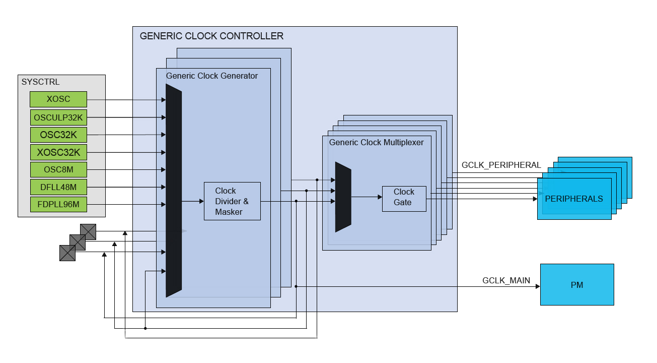
figure 1: main components of the SAMD21 clock distribution system: System Controller, Generic Clock Controller and Power Manager
The main system clock GCLK_MAIN, and clocks generated from it are called synchronous clocks, while generic clocks are called asynchronous clocks (with respect to the system closk). Peripheral access registers (the programmer’s interface) are clocked by the synchronous clock generated by the Power Manager for the peripheral; internally, the peripherals use the asynchronous clocks generated by the Generic Clock Generators (SERCOM peripheral for example uses a generic clock to source the baud rate generator). At reset the clock system is configured to use th internal 8MHz oscillator as a source for the main clock, with a prescaler of 8. The oscillator sources the Generic Clock Generator 0 to generate GCLKGEN[0] and thenGCLK_MAIN; CPU and peripheral bus clock are undivided.
GCLK: Generic Clock Controller
The Generic Clock Controller (GCLK) is composed of 9 Generic Clock Generators; each generator sources one or more Generic Clock Multiplexers (which generates Generic Clocks), one for each peripheral (GCLK_PERIPHERAL[n]). One generator can source one or more peripheral at once. GCLKGEN[0] generates GLCK_MAIN, GCLKGEN[1] can be used as clock source to other generators (except itself); GCLK_IO[n] are external clock signals (when configured as input) or the generic clock signals (when configured as output):
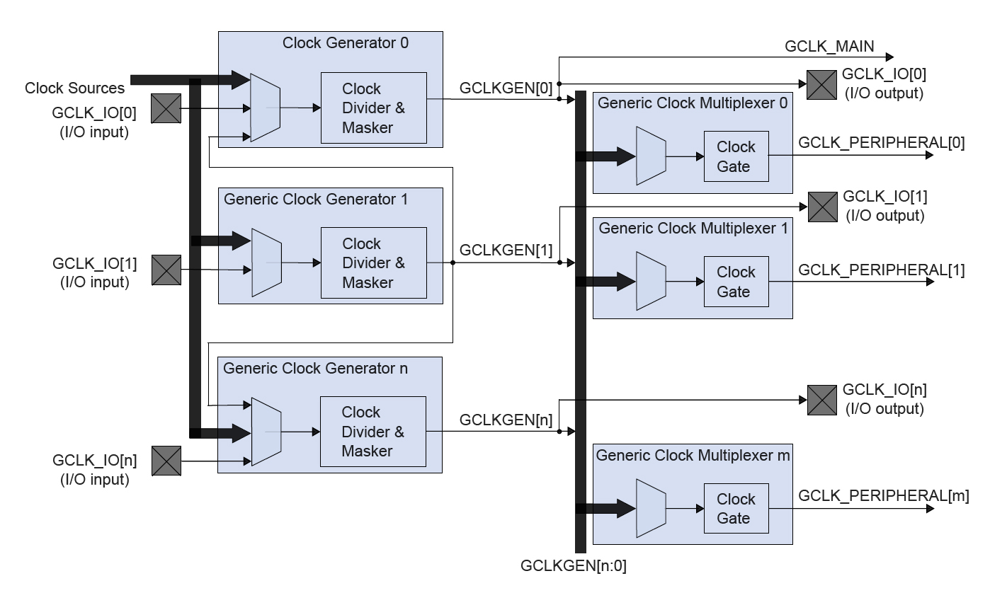
figure 2: GCLK in detail. GCLKGEN[0] is always GLCLK_MAIN, the main system clock. GCLKGEN[1] can source other generators but itself. GCLK_IO[n] are external clock signals (input) or the output of generic clocks (output)
- GENCTRL – Generic Clock Generator Control Register: GENCTRL.GENEN enables/disables the generator, GENCTRL.SRC selects the clock source (macro GCLK_GENCTRL_SRC_XXX)
- GENDIV – Generic Clock Generator Division: sets generator prescaler; 0 or 1 disables the prescaler
- CLKCTRL – Generic Clock Control Register: CLKCTRL.GEN select the generic clock generator used as source to the generic clock multiplexer (macro GCLK_CLKCTRL_GEN_GCLKn), CLKCTRL.EN enables/disables the multiplexer (each generic clock multiplexer is associated with a peripheral)
Each generator/multiplexer has its own copy of these configuration registers and they can be accessed writing the ID field of the register: GENCTRL.ID and GENDIV.ID selects the generator to be configured (from 0x00 to 0x08); CLKCTRL.ID selects the Generic Clock to be configured, alias the multiplexer linked to the peripheral to enable (macros to select the peripheral are GCLK_CLKCTRL_ID_XXX):
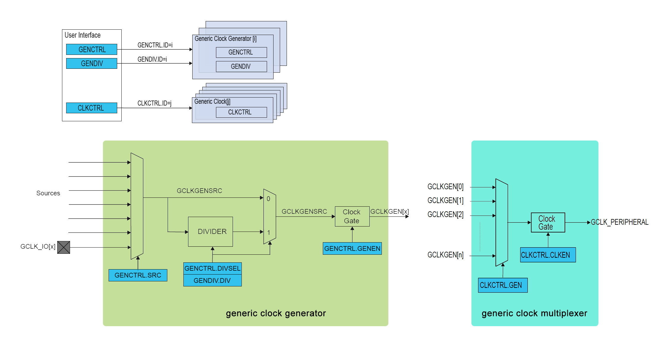
figure 3: GENCTRL e GENDIV registers configure the generic clock generators, CLKCTRL controls the multiplexers. Top: the ID field controls the access to the registers of the differnt generators/multiplexers
Each Generic Clock Generator can be sourced by one of the 9 different clock sources (excepti GLCKGEN[1] which cannot use itself as a source): those can be selected writing GENCTRL.SRC:
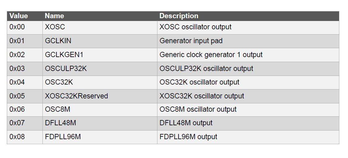
figure 4: available clock sources can be selected writing GENCTRL.SRC
Each clock source must be enabled in SYSCTRL writing the ENABLE bit in the corresponding register of SYSCTRL (ad esempio OSC8M.ENABLE). Let’s configure generic clock generator 3 with internal 8MHz oscillator (no prescaler) as a source to the SERCOM5 module:
void clock_init(void)
{
  SYSCTRL->OSC8M.bit.PRESC = 0;                          // no prescaler (is 8 on reset)
  SYSCTRL->OSC8M.reg |= 1 << SYSCTRL_OSC8M_ENABLE_Pos;   // enable source

  GCLK->GENDIV.bit.ID = 0x03;                            // select GCLK_GEN[3]
  GCLK->GENDIV.bit.DIV = 0;                              // no prescaler

  GCLK->GENCTRL.bit.ID = 0x03;                           // select GCLK_GEN[3]
  GCLK->GENCTRL.reg |= GCLK_GENCTRL_SRC_OSC8M;           // OSC8M source
  GCLK->GENCTRL.bit.GENEN = 1;                           // enable generator

  GCLK->CLKCTRL.reg = GCLK_CLKCTRL_ID_SERCOM5_CORE;      // SERCOM5 multiplexer GCLK_PERIPHERAL[n]
  GCLK->CLKCTRL.reg |= GCLK_CLKCTRL_GEN_GCLK3;           // select multiplexer source GCLK_GEN[3]
  GCLK->CLKCTRL.bit.CLKEN = 1;                           // enable generic clock

  PM->APBCSEL.bit.APBCDIV = 0;                           // no prescaler
  PM->APBCMASK.bit.SERCOM5_ = 1;                         // enable SERCOM5
}
PM: Power Manager
Power Manager controls the main clock system distribution to the CPU and the modules connected to the AHB bus and the APB buses. This clock is divided into several sub-domains (one for the CPU and AHB bus and three aothers for the APBA, APBB and APBC buses). As noted, these signal are called synchronous system clocks in order to differentiate them from the asynchronous clocks generated by the Generic Clock Generators. These clock domains can be at different speeds (as long as the CPU frequency is greater or equal to that of the other domains, and every bus is within maximum frequency) and can be enabled and disabled indipendently:
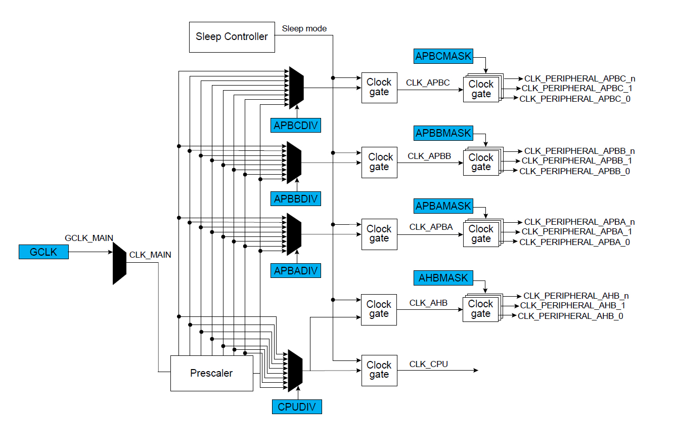
figure 5: main system clock distribution
Only a few peripheral clocks are enabled at reset in the Power Manager. In order to access configuration registers the synchronous clock must be enabled, so it’s important to make sure that the clock for the peripheral is enabled (SERCOM peripheral clock is disabled at reset for example). Configuring the Power Manager is easy: CPUSEL, APBASEL, APBSEL e APBCSEL registers select the prescaler for the different domains and AHBMASK, APBAMASK, APBBMASK e APBCMASK register enable and disable the clock for the various peripherals (component/pm.h defines macros to set/clear the specific bits). Let’s enable the clock for the SERCOM0 module:
void clock_init(void) {
    //... SYSCTRL and GCLK configuration code...
    PM->APBCSEL.bit.APBCDIV = 0; // no prescaler
    PM->APBCMASK.bit.SERCOM5_ = 1; // enable SERCOM5
}
GCLK_GEN[0] sources the GCLK_MAIN to the Power Manager which generates all the synchronous clocks for the CPU and peripherals. Generic Clock Generator GCLK_GEN[3] sources SERCOM5 generatingGLCK_PERIPHERAL[n], the asynchronous clock for the serial interface.