
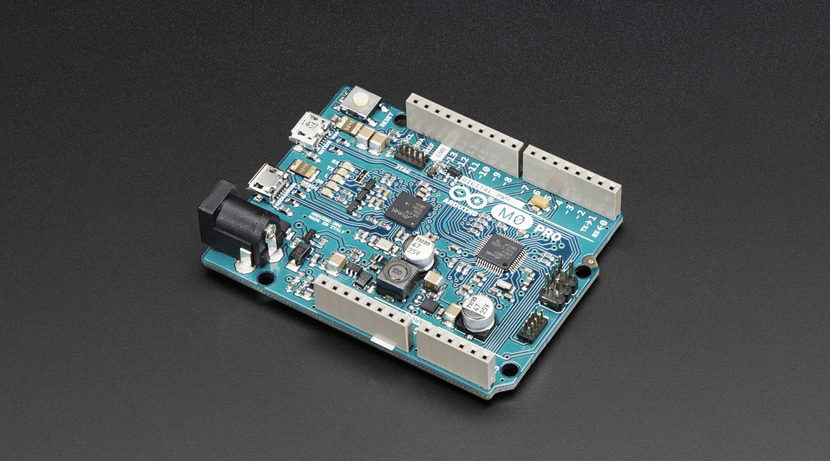
Arduino M0 PRO: programming the core ARM Cortex-M0+ and the SAMD21 MCU
A famous aphorism by computer scientist David Wheeler goes: “All problems in computer science can be solved by another level of indirection” (this is sometimes quoted as the fundamental theorem of software engineering). This principle, or concept is ubiquitous in programming: functions abstract away the implementation and expose only the interface of a piece of code, classes defines abstract data types and let us care about what those types do and not how they do it; these abstraction mechanisms provide a level of indirection that allow us to produce code that is more efficient, more reusable and more maintainable. A software driver for an embedded platform is an abstraction that provides a way to abstract away the nitty gritty detail of the hardware and is just a thin software layer, made of definitions and access functions, between the hardware and the application code.
CMSIS project for ARM Cortex-M processors

To help embedded developer write code for Cortex-M based MCUs (especially low-level code, such as peripheral drivers) and to enhance productivity and favor code maintenance and reusability and to ease integration with third party middleware (RTOS, communication stacks etc) ARM developed the CMSIS project: CMSIS stands for Cortex Microcontroller Software Interface Standard, a specification for an API interface that MCU vendors implements in their driver and that provides programmers with a standardized way to access the microcontroller hardware. CMSIS is a large project, involving low level drivers, real time operating systems and more. CMSIS – Core is that part of the specification that is currently implemented in all Cortex-M based MCU products. A CMSIS compliant driver is composed of several layers:
- Core peripheral access layer: defines names and addresses of core peripheral registers (NVIC,SysTick,MPU) and access functions for such peripherals.
- Device peripheral access layer: MCU specific, defines name and addresses of all the peripherals in the device.
- Access functions for device peripherals: this layer is implemented in the HAL software provided by the vendor of the specific MCU but ARM is promoting a project called CMSIS – Driver, that should define a standard API for peripheral access functions, but at the moment there’s no MCU vendor that implements it.
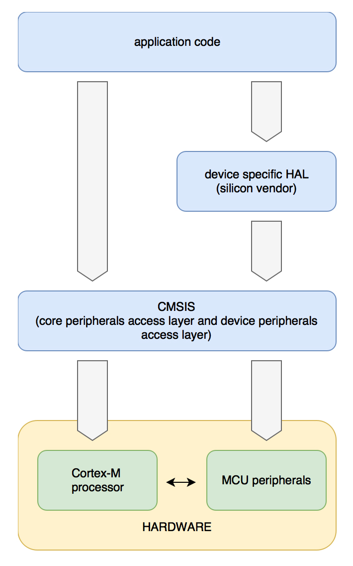
Figure 1: levels of abstration provided by CMSIS software driver and HAL
A CMSIS compliant driver and a hardware abstraction layer (both provided by the MCU vendor) are shown in figure 2. An application needs to include just <device>.h to use the CMSIS driver, or the HAL driver include file to use definitions and higher lever driver provided by the hardware abstraction layer, and the necessary files are automatically included (arrows in the diagram represent #include directives):
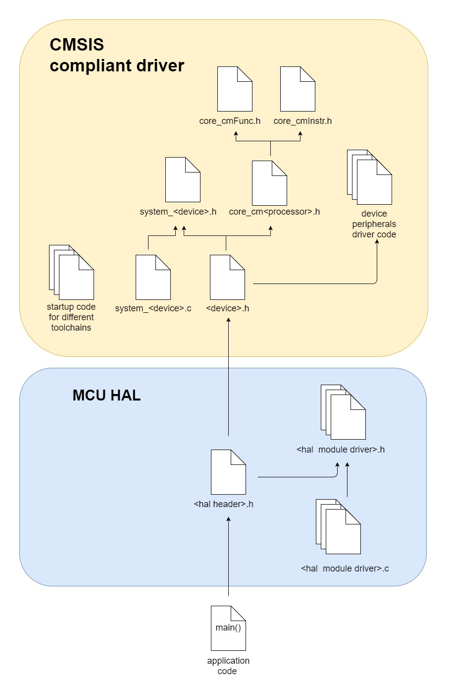
Figure 2: a project with CMSIS driver and vendor specific hardware abstraction layer (HAL)
A CMSIS compliant driver also includes files system_<device>.h/.c (where void systemInit(void), void SystemCoreClockUpdate(void) and SystemCoreClock variable are declared/defined) and the startup code (toolchain specific, can be a C file or an assembly file), which contains the vector table and default handler functions for system exception and peripheral interrupts.
Programming the peripherals from C code
All peripherals (the core peripherals and the modules of a specific MCU) are mapped into memory space (this input output model is called memory mapped IO) and therefore accessible by C pointers. The whole register set of a peripheral is mapped in memory and represents the peripheral interface. The peripheral software driver enclose the register set into a C struct and every peripheral is represented by a pointer to such a structure. A macro defines the base address of the pointer (the address of the first register in the register set) and each register can be read or written dereferencing the pointer and accessing the corresponding member of the structure. Generally a device has more instances of a peripheral, each mapped to a different memory address in IO space; in this case the driver defines a pointer for each instance of the peripheral (the structure defining the register set is the same), each pointing to the base address of the peripheral. Other macros are defined, that corresponds to the bit field of the peripheral registers:
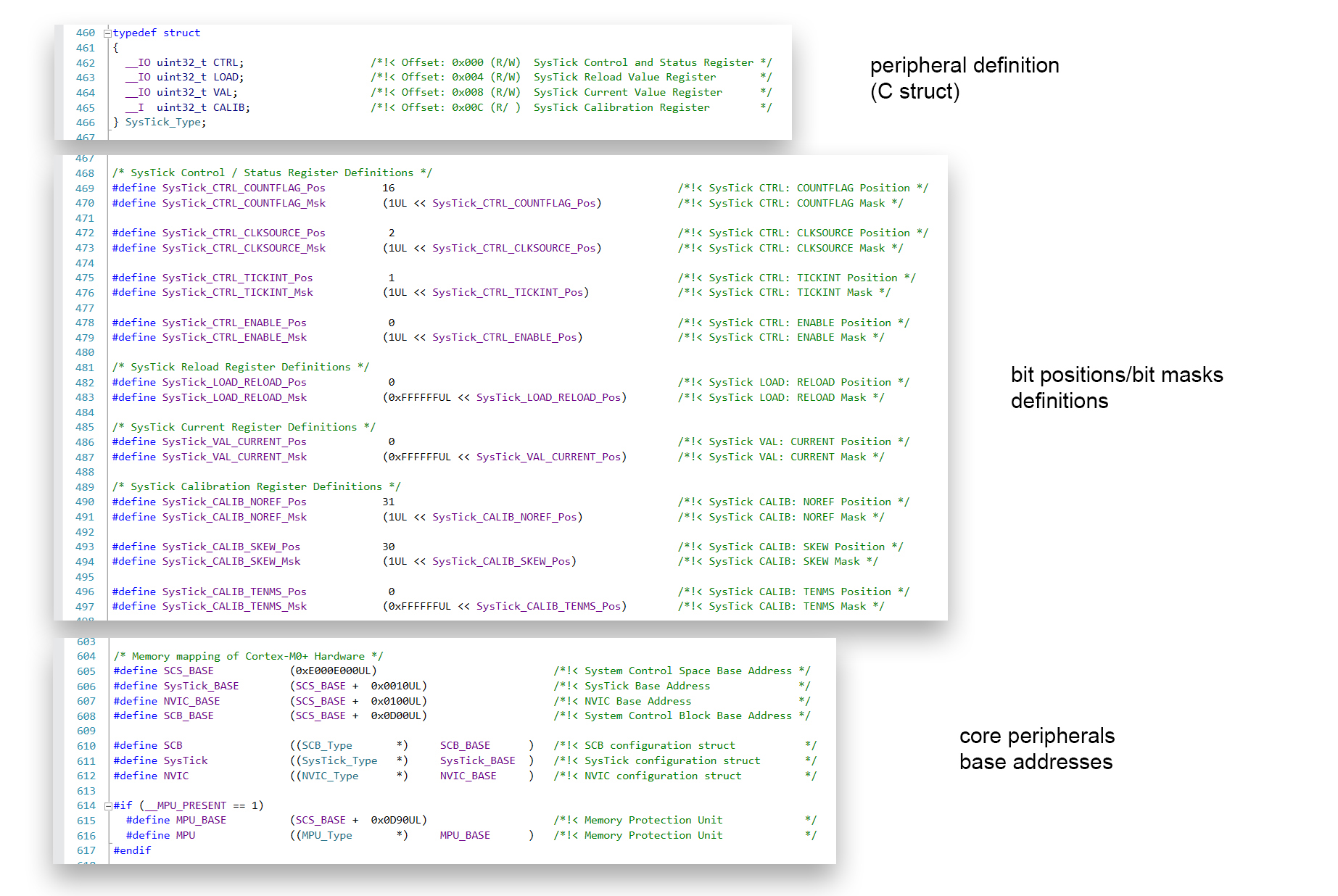
Figure 3: core peripherals definitions inside core_cm0.h
Core peripheral access layer is implemented in core_cm<processor>.h : it contains definitions of structures and addresses of all core peripherals common to all Cortex-M implementations, like NVIC and SysTick, and defines access functions fot those peripherals. Core peripherals are mapped int System Control Space (SCS), a bunch of memory addresses going from 0xE000E000 to 0xE000F000 (for a total 4 KiB). Device peripheral access layer is implemented in <device>.h and in other header files that it includes. Core peripheral layer is the same for all MCU products, while device peripheral layer is MCU specific and may differs slightly among implementations, but they mantain a similar look and feel among the various products. Mastering the device software drivers is necessary to create clear and efficient code, and in order to do so understanding the internal structure of the files is paramount. So let’s delve into the driver for the SAMD21G18A MCU, the controller onboard the Arduino M0 PRO.
SAMD21 CMSIS compliant device driver
The structure of a CMSIS compliant project for SAMD21 resembles closely the generic model shown in figure 2: <processor> is now cm0plus and the <device> is samd21g18a :
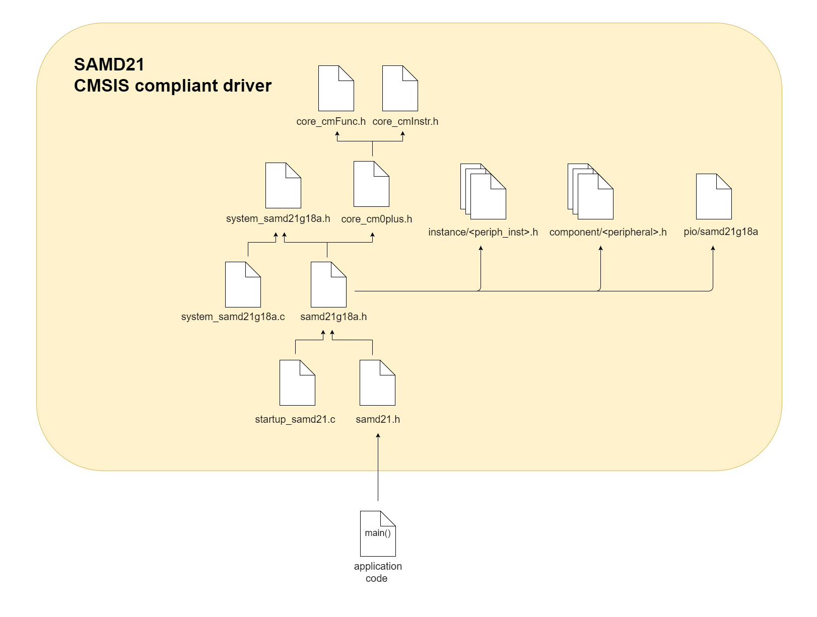
Figure 4: a CMSIS compliant project for SAMD21G18A
The main application includes samd21.h which contains a series of conditional compilation #ifdef directives and includes the specific driver file based on the device we’re programming, in thie case samd21g18a.h which among other things:
- defines enum IRQn_Type which enumerates all system exceptions and interrupt requests (IRQ); this enumerated data type is used by core_cm0plus.h (which is included after the enum definition) to access and configure NVIC (for example to enable an interrupt, or configure the interrupt priority as we’ll see in a moment)
- declare default handler functions for system exceptions and interrupts (interrupt handlers or interrupt service routines ISR)
- defines a structure called DeviceVectors, whose members are void*, which are pointers to functions defined in startup files that make the MCU Vector Table.
- defines peripheral base addresses and pointers to structures that represents peripherals.
Folders instance, component and pio contain the rest of the driver:
- the instance folder contains files that defines every register of each peripheral, one file for each instance of the peripheral:
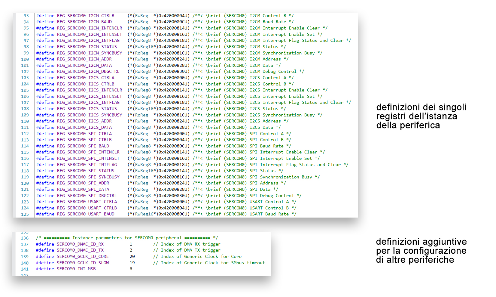
Figure 5: instance folder contains files with definitions for each register of each peripheral instance
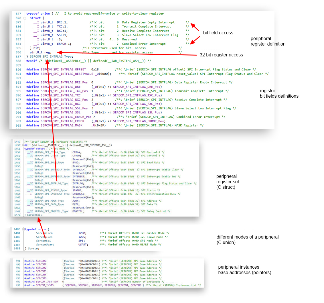
- under the component folder are files that defines structures that allows access to the device peripherals, one file for each peripheral: the peripheral register set (the whole bunch of memory mapped registers that make up the programmer’s interface to that hardware module)is enclosed into a C struct , whose members are C unions that represent each a sngle register of the peripheral; this union contains two members: a struct, whose members are the bit-fields of the register and an unsigned int (8,16 or 32 bit, depending on the register width) that allows to access the whole register. Some peripherals can be configured in different modes (SERCOM module for example can be used as USART, SPI or I2C): if that’s the case, the structures that encloses the peripheral registers for each mode are themselves encapsulated into a union. In the end, peripheral base addresses and pointers to these peripherals are defined in samd21g18a.h (figure 6):
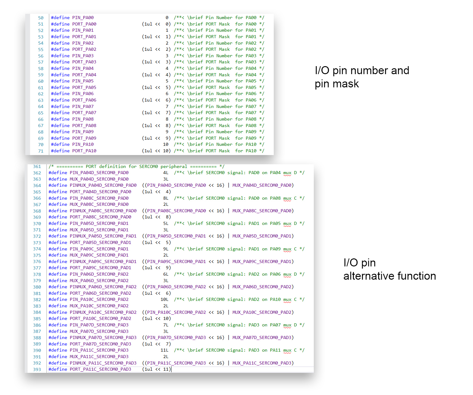
- a file named samd21g18a.h is contained in the pio folder (same name as the device include file for the driver, but distinct) and contains IO pin definitions for the MCU: the pins are grouped into ports of 32 pins (PORTA, PORTB etc..) and the exact number of exposed pins depends on the specific MCU product. The SAMD21G18A has 32 pin on PORTA/group 0 (from PORT_PA00 to PORT_PA31) and 24 pin on PORTB/ group 1 (from PORT_PB00 to PORT_PB23). This files also defines macros to configure alternative functions for the IO pins:
Now that we’ve had a brief look at how a software device driver is structured we’re ready for a simple application. The official development environment for ARM based Atmel/microchip MCUs is Atmel Studio, which uses a GNU-ARM toolchain to build projects. Let’s create a new project under File->New->Project->GCC C Executable Project eand choose SAMD21G18A as device. The main file must include samd21g18a.h in order to use the CMSIS driver (the header will automatically include all the necessary files). Function main() calls systemInit(), declared in system_samd21g18a.h and defined in system_samd21g18a.c . This file is under the folder Device_Startup along with startup code file startup_samd21g18a.c. No system configuration is performed at the moment, we’ll see later how to configure SysTick, NVIC and more importantly the clock.
PORT: IO pin controller
The module PORT – IO pin controller controls the IO pins:
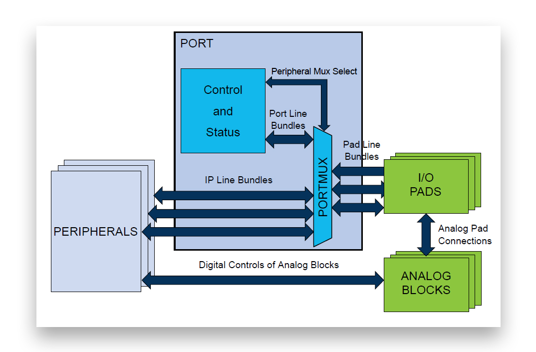
Figure 8: block diagram of PORT peripheral (from SAMD21 datasheet)
PORT peripheral has the following registers:
- DIR (DIRCLR/DIRSET/DIRTGL) DATA DIRECTION: each bit is a pin, 0 if the pin is input, 1 if it’s output. Writing the register requires a read/modify/write operation; DIRCLR (data direction clear), DIRSET (data direction set) and DIRTGL (data direction toggle) allow atomic access.
- OUT (OUTCLR/OUTSET/OUTTGL) DATA OUTPUT VALUE: each bit is the output value of the corresponding pin (if configured as output); OUTCLR, OUTSET e OUTTGL allow atomic access.
- IN DATA INPUT VALUE: each bit reads the input value of the corresponding pin (configured as input).
- PMUXn (n = 0,…,15) PERIPHERAL MULTIPLEXING n: every pin can be assigned to a peripheral of the MCU; every pin can have up to 15 alternative functions , represented by a letter (SAMD21G18A implements only 9, from A to I). Each register controls two consecutive pins (16 bit/pin).
- PINCFGn (n = 0,…,31) PIN CONFIGURATION: these register configures pullup resistors and enables peripheral pin multiplexing.
As said MCU pins are organized into two groups of max 32 pins each and the SAMD21G18A exposes 32 pins on PORTA and 24 on PORTB. Just a few of them are exposed on the Arduino board (pay attention to the different numbering of the pins on the board):
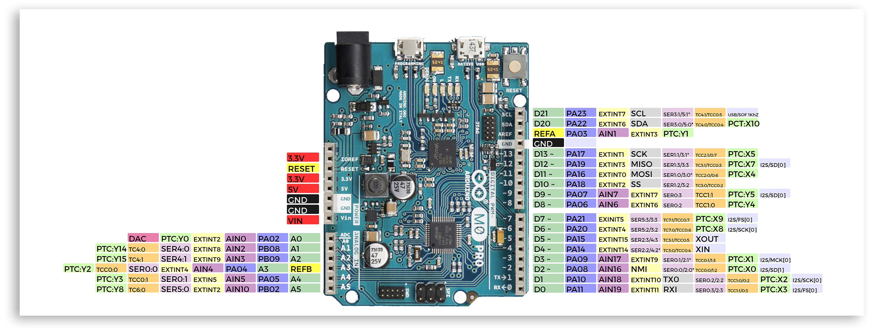
Figure 9: Arduino M0 PRO pinout and corresponding SAMD21G18A pin numbering scheme and alternative functions.
component/port.h defines PortGroup, a structure containing the register set of an instance (port or group) of PORT peripheral. Each instance is a group of (max 32) pins and the two instances are accessed from another structure called Port which has a single array member called Group, which contains two PortGroup structures (two instances of PORT peripheral are consecutively mapped, PORTA is Group[0], PORTB is Group[1]); the base address of the Port structure is defined as PORT nel file samd21g18a.h (as all other peripheral base addresses). Arduino pin 13 is connected to the user led on the board (near serial tx and rx leds, marked with L) and corresponds to pin 17 of PORTA of SAMD21 and defined in pio/samd21g18a.h as PORT_PA17. Let’s configure the pin as output and use it to blink the led:
#include "samd21g18a.h"

void port_init(void);
void blink(void);

int main(void)
{
  SystemInit();
  port_init();

  while (1)
  {
    blink();
  }
}

void port_init(void)
{
  PORT->Group[0].DIR.reg |= PORT_PA17;        // pin PA17 is output
}

void blink(void)
{
  PORT->Group[0].OUT.reg |= PORT_PA17;        // pin high
  for (int i = 0 ; i < 100000; i++)           // delay
    ;
  PORT->;Group[0].OUT.reg &= ~(PORT_PA17); // pin low
  for (int i = 0 ; i < 100000; i++)
    ;
}
As an alternative it’s possible to use instance/port.h to configure the pin:
#include "samd21g18a.h"

void port_init(void);
void blink(void);

int main(void)
{
  SystemInit();
  port_init();

  while (1)
  {
    blink();
  }
  }

void port_init(void)
{
  REG_PORT_DIR0 |= PORT_PA17;
}

void blink(void)
{
  REG_PORT_OUT0 |= PORT_PA17;
  for (int i = 0 ; i < 10000; i++)
    ;
  REG_PORT_OUT0 &= ~(PORT_PA17);
  for (int i = 0 ; i < 10000; i++)
    ;
}