
Interfacing a PS/2 keyboard to a microcontroller
In this article I explain how to interface a PS/2 keyboard to a microcontroller. Reading characters from a keyboard is just a matter of understanding the PS/2 protocol which is quite easy to implement. To communicate with a keyboard we must connect it somehow to the micro.
The electrical interface and the connector
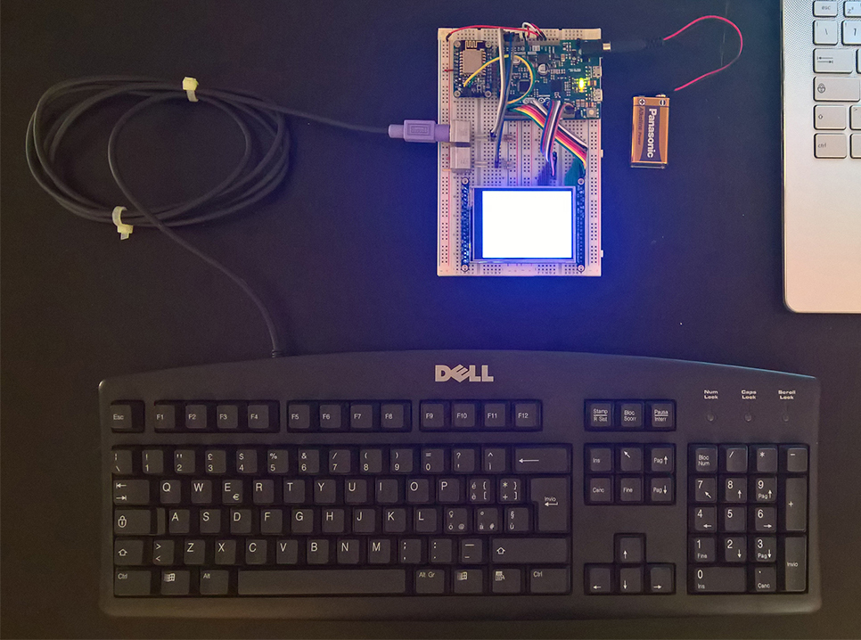
The physical PS/2 port is the is the 6-pin DIN connector. The connector pinout is shown below:
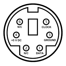
figure 1: the PS/2 6-pin DIN socket
Vcc/Ground provide power to the device (5V) while Data and Clock are two open collector lines with pullup resistors to Vcc. The resistor value is not important (1 – 10 KOhm), smallest values give smallest rising time while larger values allow for less power consumption. I use a PCB connector and repurpose it so I can use it with a prototyping breadboard in my projects:
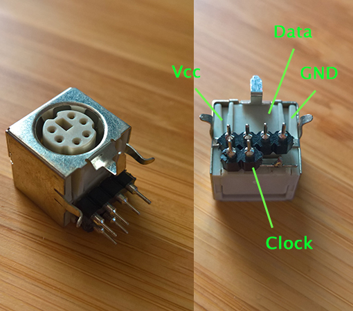
figure 2: a PCB PS/2 connector hacked for breadboard prototyping
The PS/2 protocol
The PS/2 protocol is a bidirectional serial synchronous protocol. When the data and clock lines are high the bus is idle and the keyboard/mouse can begin transmitting data; the host can inhibit transmission at any time by pulling the clock line low for 100 microseconds. The device always generates the clock signal and if the host wants to communicate it can do so by pulling the clock line low (inhibiting transmission by the device), pulling the data line low and then releasing the clock line: this is the request to send state and tells the device to start generating clock pulses. A data frame is made of 11 or 12 bits (depending on data direction):
- a start bit (always low)
- 8 data bits, LSB first
- a odd parity bit
- a stop bit (always high)
- an acknowledge bit (the device pulls the data line low when transmitting from host to device)
Device to host communication
The device checks the state of the clock line: if it is high it starts transmitting data (the clock line must be continuously high for at least 50 microseconds before the device starts transmitting). The device generates the clock pulses and the data must be stable on the falling edge of the clock signal and change after the rising edge:
figure 3: device to host communication diagram
The time from data transition to a falling edge of the clock signal must be greater than 5 microseconds and less than 25 microseconds while the time from a rising edge of the clock signal to the data transition must be at least 5 microseconds (so we can sample the data during the low period of the clock signal, while data changes during the high period). If the host inhibits the transmission by pulling the clock low for 100 microseconds before the 11th clock pulse the device must resend the frame when the clock line is high again (and communication is no longer inhibited by the host). Any data that is created while communication is inhibited must be buffered (keyboards have a 16-byte buffer for that purpose, while mice only store current movement packet).
Host to device communication
Since the device always generates the clock signal the host must put the clock and data lines in the request to send state by pulling the clock line low for 100 microseconds and then pulling the data line low and pulling clock line high again (a). When the device detects this state it will begin to generate clock pulses and will clock in the data bits of the frame (b): the host changes data when the clock is low and the device samples the data line when the clock is high (this is the opposite of what happens during device to host communication):
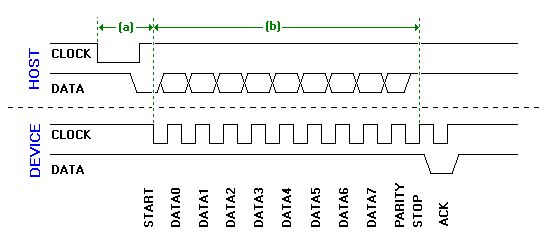
figure 4: host to device communication diagram
After clocking in the stop bit the device pulls the data line low to acknowledge the data, then generates the last clock pulse and release data and clock lines. Host to device communication is useful to send commands to the keyboard.
Interfacing a PS/2 keyboard
A keyboard is a matrix of keys which are monitored by an on-board controller, called the keyboard encoder. This controller monitors which key is pressed or released and send the corresponding data to the host. The data sent by the controller to the host is the scan code (the controller scans the keyboard for keypresses) of the key which has been pressed or released. There are two kinds of codes: the make code and the break code. A make code is sent whenever a key is pressed or held down; a break code is sent when a key is released. Every key on the keyboard has its unique make and scan code so the host can know what happened to which key by looking at the scan code. All the scan codes make up a scan code set: there are three scan code sets (set one, two or three), and all modern keyboards default to scan code set two:
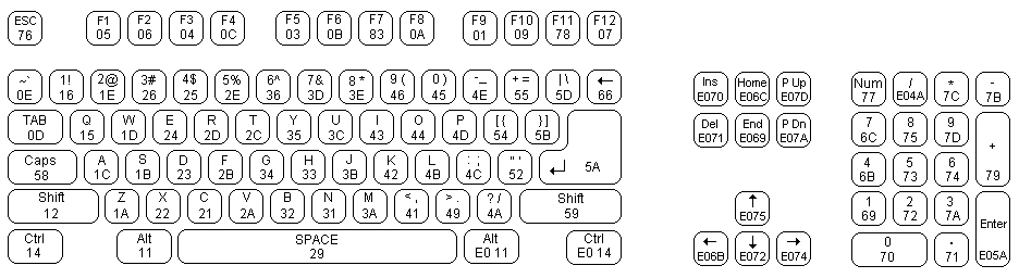
figure 5: scan code set 2
Even if most make codes are one byte long there are some extended make codes that are made up of two or four bytes (all these scan codes begin with the byte 0xE0). Whenever a key is pressed a scan code is sent to the host. It’s important to note that a scan code corresponds to a physical key on the keyboard and is not associated with a character of a particular character set and it’s up to the host to translate the scan code to the matching character. When a key is released a break code is sent to the host: the break code is the make code preceded by 0xF0 (extended keys break code is 0xE0, 0xF0 and the code for the key).
When a key is held down that key becomes typematic and (after a short while) the keyboard will keep sending its make code until it is released or another key is pressed. Typematic data is not buffered inside the keyboard: when more than one key is pressed only the last key becomes typematic and the typematic repeat stops whet it is released even if other keys might still be pressed.
At reset the keyboard performs what is called a BAT (Basic Assurance Test) and sends 0xAA if successful or 0xFC if failed (the leds on the keyboard flash if any).
Reading scan codes from the keyboard
The easiest way to read data sent from a PS/2 keyboard is to use external interrupts. All microcontrollers allow to trigger an interrupt when a specific event occurs on an external pin and most of them have a dedicated external interrupt controller. During device to host communication the host samples the data line when the clock is low, so it’s easy to set up a trigger when the pin connected to the clock line goes low and read the scan code from the keyboard. The ISR simply calls keyboard_handler() which reads the scan code and then calls keyboard_decode(), which translates the scan code to a character (an array is used as a look-up table) and puts it into a FIFO buffer:
static void keyboard_decode(char scan_code)
{
	static int shifted = 0;
	static int released = 0;
	if (released)  // last key was a break code
	{
		switch (scan_code)
		{
			case 0x59:
			case 0x12:
				shifted = 0;
				break;
			default:
				break;
		}
		released = 0;
	}
	else
		switch (scan_code)
		{
			case 0x59:  // right shift
			case 0x12:  // left shift
				shifted = 1;
				break;
			case 0xF0:  // break code
				released = 1;
				break;
			default:
                                int i;
				for (i = 0 ; scan_code != scan_codes[i][0] ; i++)
				    if (scan_codes[i][0] == 0)
					break;
			        if (scan_code == scan_codes[i][0])
				if (shifted)
					keyboard_put_key(scan_codes[i][2]);
				else
					keyboard_put_key(scan_codes[i][1]);
				break;
		}
}

void keyboard_Handler(void)
{
	static int bitcount = 0;
	static unsigned char data = 0x00;
	if (bitcount > 0 && bitcount < 9)
	{
		data >>= 1;
		if (PORT->Group[0].IN.reg & PORT_PA18)  // this is for SAMD21 - replace with data from clock pin
			data |= 0x80;
	}
	if (bitcount++ == 10)
	{
		keyboard_decode(data);
		bitcount = 0;
		data = 0x00;
	}
}

char scan_codes[][3] =
{
	0x0e,'|',' ',
	0x15,'q','Q',
	0x16,'1','!',
	0x1a,'z','Z',
	0x1b,'s','S',
	0x1c,'a','A',
	0x1d,'w','W',
	0x1e,'2','"',
	0x21,'c','C',
	0x22,'x','X',
	0x23,'d','D',
	0x24,'e','E',
	0x25,'4','$',
	0x26,'3','£',
	0x29,' ',' ',
	0x2a,'v','V',
	0x2b,'f','F',
	0x2c,'t','T',
	0x2d,'r','R',
	0x2e,'5','%',
	0x31,'n','N',
	0x32,'b','B',
	0x33,'h','H',
	0x34,'g','G',
	0x35,'y','Y',
	0x36,'6','&',
	0x39,',',';',
	0x3a,'m','M',
	0x3b,'j','J',
	0x3c,'u','U',
	0x3d,'7','/',
	0x3e,'8',' ',
	0x41,',',';',
	0x42,'k','K',
	0x43,'i','I',
	0x44,'o','O',
	0x45,'0','=',
	0x46,'9',' ',
	0x49,'.',':',
	0x4a,'-','_',
	0x4b,'l','L',
	0x4c,'ø',' ',
	0x4d,'p','P',
	0x4e,'+','*',
	0x52,'æ',' ',
	0x54,'å',' ',
	0x55,'\\',' ',
	0x5a,'\r','\r',
	0x5b,'¨',' ',
	0x5d,'\'',' ',
	0x61,'<','>',
	0x66,'\b','\b',
	0x69,'1',' ',
	0x6b,'4',' ',
	0x6c,'7',' ',
	0x70,'0',' ',
	0x71,',',' ',
	0x72,'2',' ',
	0x73,'5',' ',
	0x74,'6',' ',
	0x75,'8',' ',
	0x79,'+',' ',
	0x7a,'3',' ',
	0x7b,'-',' ',
	0x7c,'*',' ',
	0x7d,'9',' ',
	0,'\0','\0',
};
Then the application just needs to get the characters which are stored into the FIFO buffer and process them. In my project I’m implementing a simple shell for the SAMD21G18A and I print the characters on the screen and process them to send commands to the microcontroller:
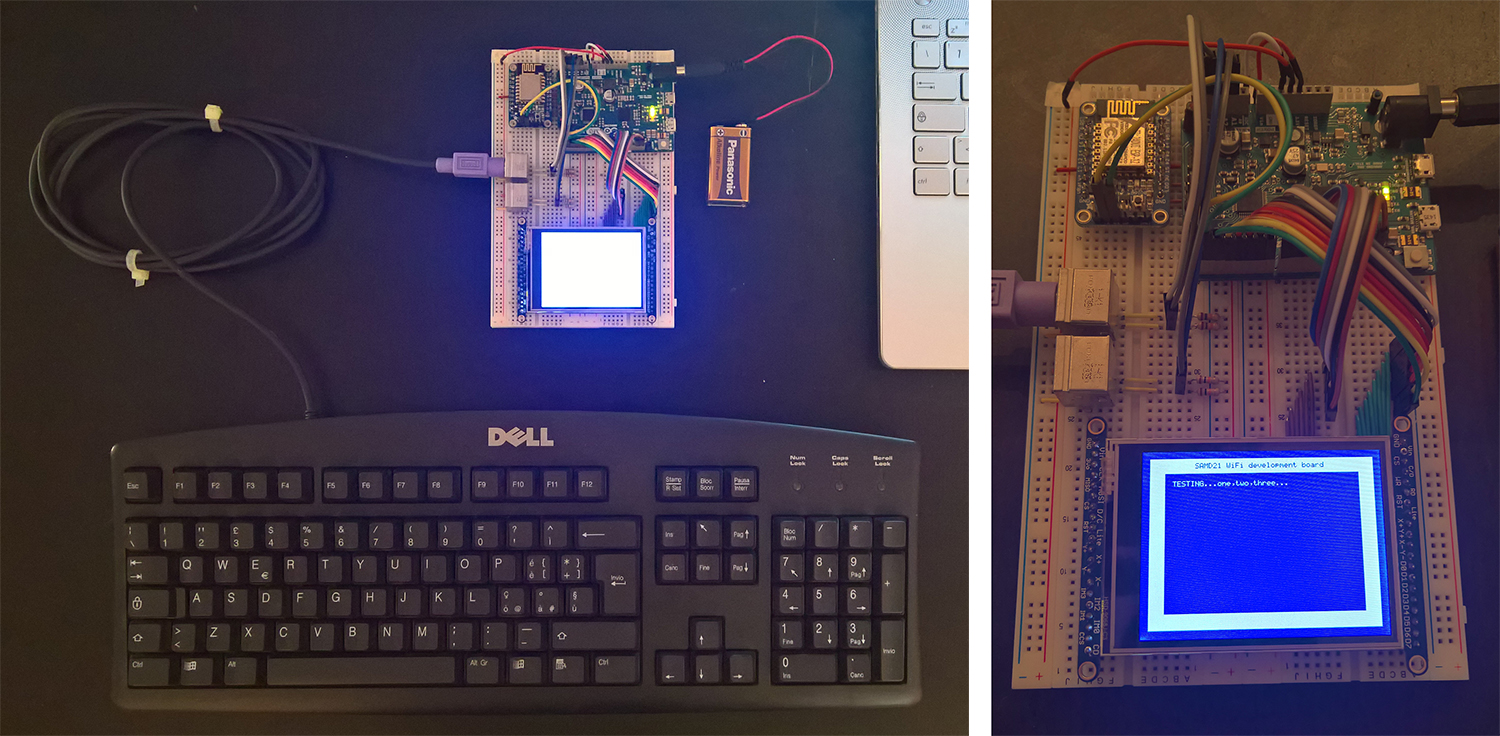
figure 6: my project with a SAMD21G18A with a TFT display and two PS/2 connector