
WiFi controlled Neo Pixels strips
In this project I explain how to drive NeoPixels with an Arduino M0 PRO (SAMD21) using the SPI peripheral with the DMA controller to create colored animated patterns. Since displaying simple animation is boring, I’ll show how to send commands over a WiFi connection in order to change the colored patterns created with the leds. Making all these components work together in a timely fashion inside the application is not trivial. Using the SPI with direct memory access offloads some work from the CPU to the DMA controller, but listening for commands over the UART from the WiFi module while updating the animation requires careful planning of the CPU usage. The simplest approach, the one shown here, is to use a classic superloop, or infinite-loop and ISRs.
Driving NeoPixels with the SPI
NeoPixels are integrated light sources in which a RGB led is packaged with a driver chip (the WS2812/WS2812B or the SK6812) and controlled by a single-wire. They can be used singularly or most often come in strips of a variable number of elements. The protocol is simple, a 24-bit RGB color (8 bits per color) is sent through the only data wire with a timing specified in the chip datasheet: data transmission is allowed up to 800KHz and coding a 0 or a 1 is just a matter of generating a square wave with the correct duty cycle:
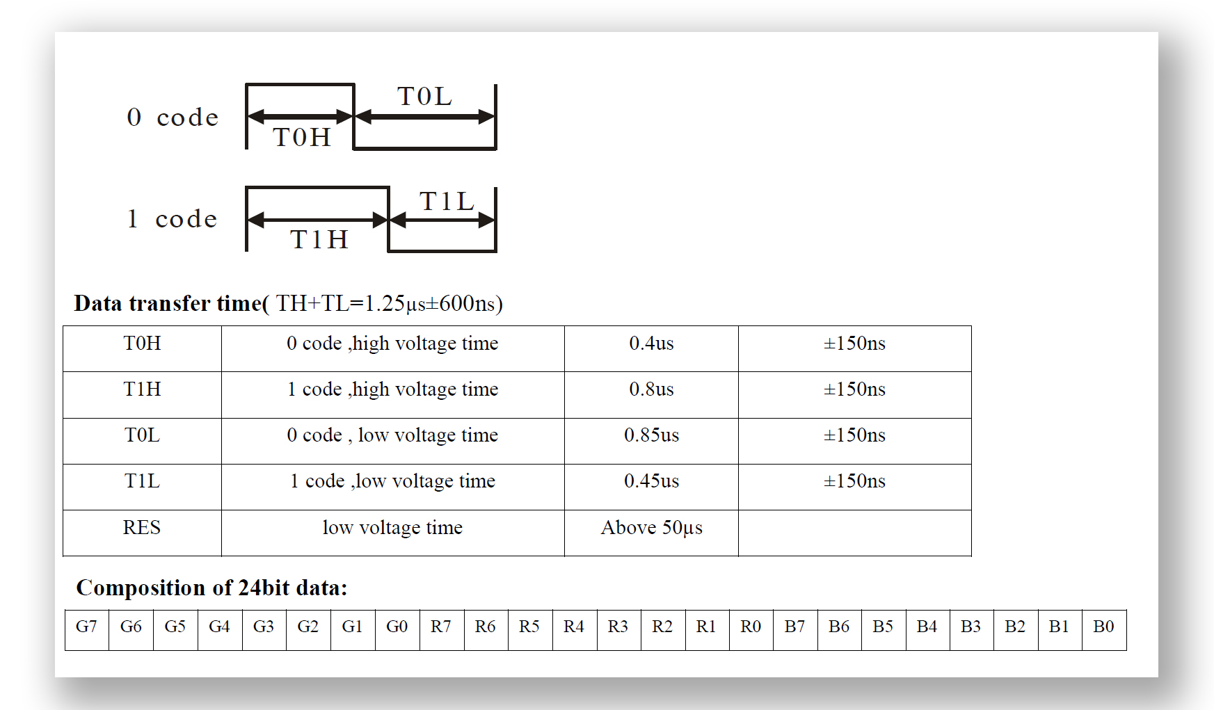
figure 1: coding of 0 and 1 signals, timing characteristics and order of color data
If we need to drive a strip of leds we need to send the color for the first led, then the second and so on until the color for the last led of the strip has been sent. When we’re done we simply latch the data by sending a 300 microseconds worth of zeroes, then the leds lights up. Timing is not very strict (the chip allows for little tolerance) and different driver chips specify different timing characteristics but they all work the same (see the datasheet for the various driver chips at the end of the article). Since timing is so crucial we could write some time-critical code in assembly to toggle the level of the data pin in order to generate the correct signal to drive the leds. This approach would be difficult to integrate with the other components, since we want to animate the leds and at the same time the application need to listen for commands over the UART (and possibly do something else). Since the datasheet allows for a little tolerance in the signal timing we can use the SPI to generate a bit pattern that resembles the square wave that corresponds to a zero or a one code. Each bit is expanded into three bits: if we want to send a 1 code we send a 110 pattern, if we want to send a 0 code we send a 100 pattern, while the SPI is configured with a speed of 800 KHz * 3 = 2.4 MHz:
figure 2: bit code expansion into a three-bits pattern
At the end of the data we need to provide the latch signal, so the SPI will send 90 bytes filled with zeroes. We send data using the direct memory access capability of the SAMD21, freeing the CPU from loading the SPI register with data. So if the strip contains N leds we need a buffer of N * 3 * 3 (each led needs three bytes and each bit is expanded into three bits) + 90 bytes for latching. Since it’s from this buffer that the DMA controller fetches the data for the SPI I’ll call it the DMA buffer. Another buffer is created which is used as a framebuffer and is updated by the application: this buffer contains just the original color data (3 bytes per led pixel), so it’s easy to read from and write to (in the same way a display framebuffer is updated); each byte in this framebuffer is then expanded into three bytes by indexing into a lookup table (the table has 256 entries, one for each possible byte) and copied into the DMA buffer, ready to be sent out by the SPI:
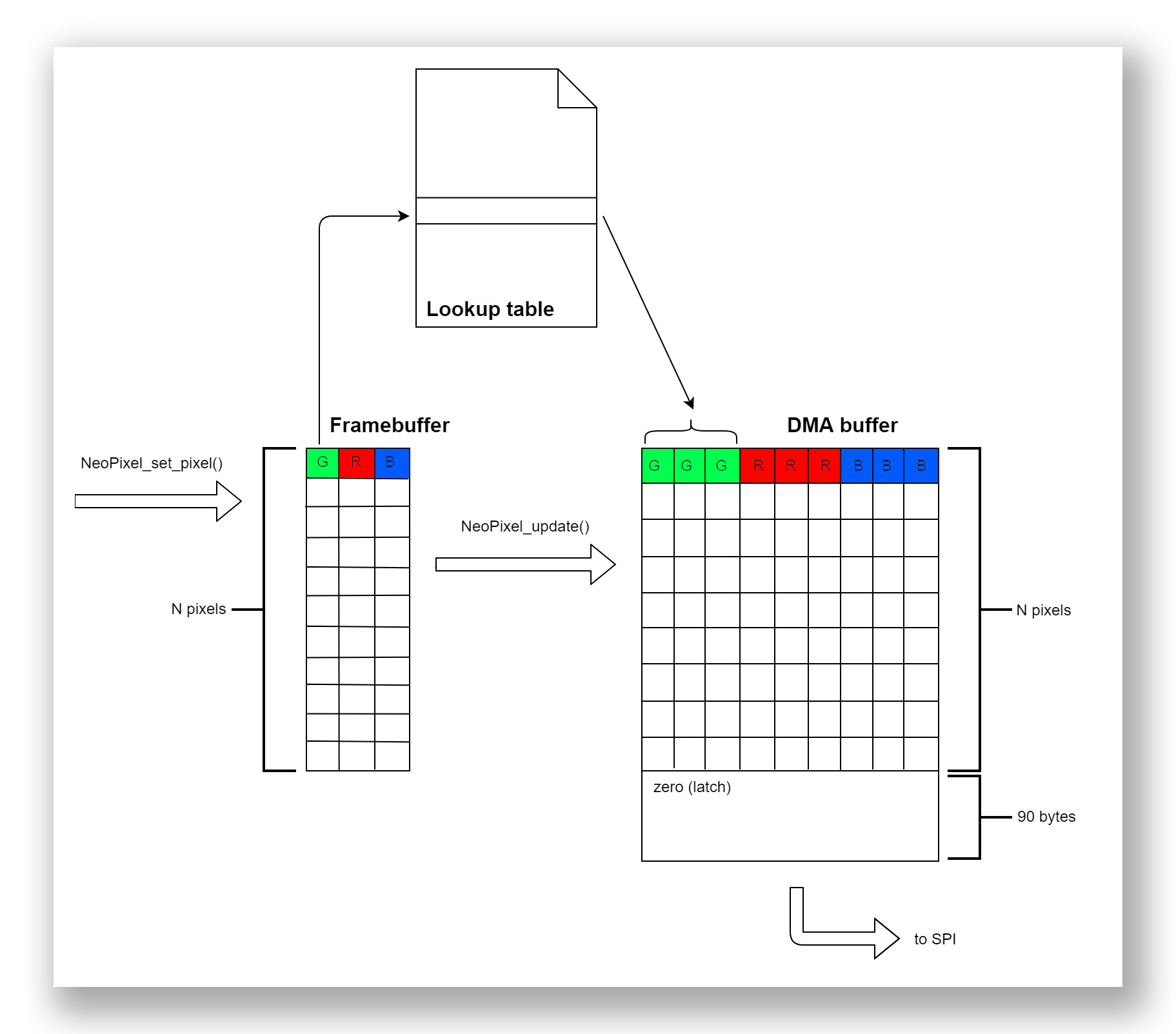
figure 3: the pixel framebuffer is expanded into the DMA buffer that is sent to the SPI peripheral by the DMA controller
The DMA controller
The DMA controller of the SAMD21 allows all kinds of data transfer (peripheral to memory, memory to peripheral, memory to memory and peripheral to peripheral), has 12 configurable channels and use transfer descriptors to configure the tranfers. The DMA controller is configured to receive requests from the SPI peripheral whenever it need to send data (the SPI triggers DMA data transfers). Data is tranferred from the DMA buffer to the SPI data register continuously (one byte at the time) even if the data stays the same (to avoid glitches in the light patterns); the DMA channel is re-enabled after each DMA transfer complete interrupt. I provide a simple way to add channels to the DMA controller, even if in this application we need only one for the SPI:
#define MAX_DESCRIPTORS 2

/* statically allocated arrays of DMA transfer descriptors (descriptor section and write back section */
__attribute__((__aligned__(16))) static DmacDescriptor descriptor_section[MAX_DESCRIPTORS];
__attribute__((__aligned__(16))) static DmacDescriptor write_back_section[MAX_DESCRIPTORS];
static int used_channels = 0;  // used channels

int volatile dma_frame = 0;

void DMA_init(void)
{
	static int initialized = 0;

	if (!initialized)
	{
		/* enable peripheral clock */
		PM->APBBMASK.bit.DMAC_ = 1;

		/* enable AHB master clock */
		PM->AHBMASK.bit.DMAC_ = 1;

		/* configure DMA controller */
		DMAC->BASEADDR.reg = (uint32_t)descriptor_section;                    // descriptor memory section start
		DMAC->WRBADDR.reg = (uint32_t)write_back_section;                     // descriptor write-back memory section start
		DMAC->CTRL.bit.LVLEN0 = 1;                                            // enable level 0 priority
		DMAC->CTRL.bit.LVLEN1 = 1;                                            // enable level 1 priority
		DMAC->CTRL.bit.LVLEN2 = 1;                                            // enable level 2 priority
		DMAC->CTRL.bit.LVLEN3 = 1;                                            // enable level 3 priority

		/* DMA is initialized */
		initialized = 1;
	}
}

/* add the first least significant free channel with its descriptor */
void DMA_add_channel(int source, DmacDescriptor *descriptor)
{
	/* disable DMA if enabled */
	if (DMAC->CTRL.bit.DMAENABLE)
		DMAC->CTRL.bit.DMAENABLE = 0;
	while (DMAC->CTRL.bit.DMAENABLE)
		;

	/* add transfer descriptor to transfer descriptor section (before enabling channel!) */
	memcpy(descriptor_section + used_channels * sizeof(DmacDescriptor), descriptor, sizeof(DmacDescriptor));

	/* configure and enable first least significant free channel */
	DMAC->CHID.bit.ID = used_channels++;                                  // use first free channel
	DMAC->CHCTRLB.bit.LVL = 0x00;                                         // channel priority level 0
	DMAC->CHCTRLB.bit.TRIGACT = 0x02;                                     // one trigger each beat transfer
	DMAC->CHCTRLB.bit.TRIGSRC = source;                                   // select trigger source
	DMAC->CHCTRLA.reg |= DMAC_CHCTRLA_ENABLE;                             // enable channel

	/* enable DMA block transfer complete interrupt */
	DMAC->CHINTENSET.bit.TCMPL = 1;                                       // enable DMA block transfer complete interrupt
	NVIC_EnableIRQ(DMAC_IRQn);                                            // enable DMA interrupt in NVIC
}

void DMA_enable(void)
{
	/* enable DMA controller */
	DMAC->CTRL.bit.DMAENABLE = 1;
}

void DMAC_Handler(void)
{
	for (int channel = 0 ; channel < used_channels ; channel++)  // check interrupt for every registered channel
	{
		DMAC->CHID.bit.ID = channel;
		if (DMAC->CHINTFLAG.bit.TCMPL && DMAC->CHINTENSET.bit.TCMPL)
		{
			if (DMAC->CHID.bit.ID == 0x00)   // handle SPI transfer complete interrupt
			{
                            DMAC->CHINTFLAG.bit.TCMPL = 1;                 // acknowledge interrupt
			    DMAC->CHCTRLA.reg |= DMAC_CHCTRLA_ENABLE;      // re-enable DMA channel
                        }
		}
	}
}
A section in RAM is allocated for transfer descriptors (in this application we need just one but it can be extended to as many descriptors as needed). A DMA channel is configured and added for the SPI in the NeoPixel_init() function inside the NeoPixel.c file:
static uint8_t pixel_buffer[NUM_PIXELS * 3];             // 3 bytes per pixel (G-R-B)
static uint8_t dma_buffer[NUM_PIXELS * 3 * 3 + 90];      // each byte is expanded to 3 bytes + 90 bytes (zeros) for latching

void NeoPixel_init(void)
{
	/* initialize frame buffer */
	NeoPixel_clear_pixels();

	/* initialize DMA buffer */
	for (int i = 0 ; i < sizeof dma_buffer ; i++)
		dma_buffer[i] = 0x00;

	/* configure and enable DMA controller */
	/* set up transfer descriptor */
	DmacDescriptor descriptor;
	descriptor.DSTADDR.reg = (uint32_t)&SERCOM0->SPI.DATA;                // destination address is SPI DATA register
	descriptor.SRCADDR.reg = (uint32_t)(dma_buffer + sizeof dma_buffer);  // source address is the DMA buffer
	descriptor.DESCADDR.reg = 0;                                          // only one transfer descriptor
	descriptor.BTCTRL.bit.BEATSIZE = DMAC_BTCTRL_BEATSIZE_BYTE_Val;       // beat size is one byte
	descriptor.BTCTRL.bit.DSTINC = 0;                                     // destination address increment disabled
	descriptor.BTCTRL.bit.SRCINC = 1;                                     // source address increment enabled
	descriptor.BTCTRL.bit.STEPSEL = DMAC_BTCTRL_STEPSEL_SRC_Val;          // flexible source address increment size
	descriptor.BTCTRL.bit.STEPSIZE = DMAC_BTCTRL_STEPSIZE_X1_Val;         // source address increment is one byte
	descriptor.BTCTRL.bit.BLOCKACT = DMAC_BTCTRL_BLOCKACT_NOACT_Val;      // request interrupt at end of block transfer
	descriptor.BTCNT.reg = sizeof dma_buffer;                             // beat count
	descriptor.BTCTRL.bit.VALID = 1;                                      // descriptor is valid
	/* initialize DMA controller */
	DMA_init();
	/* add and enable SERCOM0 (SPI) channel */
	DMA_add_channel(DMA_SOURCE_SERCOM0, &descriptor);
	/* enable DMA */
	DMA_enable();

	/* initialize SPI */
	SPI_init();
}
So, at the beginning both the DMA buffer and the frame buffer (here called pixel_buffer) are empty (filled with zeroes, all leds off). The DMA is initialized, a channel linked to the SPI (SERCOM0) is added and the SPI initialized and enabled. The NUM_PIXELS macro is defined in NeoPixel.h to select how many pixels the strip is made of. At this point the SPI is sending the contents of the DMA buffer on the data line, but we still have to “draw” on the framebuffer to display light patterns. The fundamental function is NeoPixel_set_pixel():
/* set pixel color (pixel are numbered from 0 to NUM_PIXELS - 1) */
void NeoPixel_set_pixel(int pixel, uint8_t red, uint8_t green, uint8_t blue)
{
	if (pixel < 0 || pixel >= NUM_PIXELS)
		return;
	int n = pixel * 3;
	pixel_buffer[n] = green;
	pixel_buffer[n + 1] = red;
	pixel_buffer[n + 2] = blue;
}
After checking that the selected pixel is in range, the function draw the selected color into the framebuffer. To display the updated buffer we need to call NeoPixel_update(), which copies the pixel buffer into the DMA buffer, expanding the bytes by performing a table lookup into the expand array (the index into the expand array is the byte itself):
static const uint32_t bit_expand[256]; // lookup table for bit expansion

/* update DMA buffer */
void NeoPixel_update(void)
{
	for (int i = 0, j = 0 ; i < sizeof pixel_buffer ; i++, j += 3)
	{
		uint32_t expanded = bit_expand[pixel_buffer[i]];
		dma_buffer[j] = expanded >> 16;
		dma_buffer[j + 1] = expanded >> 8;
		dma_buffer[j + 2] = expanded;
	}
}

/* bit expansion lookup table */
static const uint32_t bit_expand[256] = {
	0b100100100100100100100100,
	0b100100100100100100100110,
	0b100100100100100100110100,
	0b100100100100100100110110,

        ..... other entries
        .....
};
The DMA continuously transfers data from the DMA buffer to the SPI data register, so as soon as the NeoPixel_update() function executes the leds are updated with the contents of the pixel buffer.
Animating the pixels: the timer
The NeoPixel_update_animation() function updates the pixel framebuffer with a new frame of the animation. This function is called in the infinite loop of the main() function. To display a smooth animation the buffer should be updated 30 times per second, so we need a timer that generates a periodic interrupt that will serve as a timebase for the animation. Configuring the Timer/Counter of the SAMD21 is easy (the clock is configured to run at 48 MHz from GCLK_GEN0):
volatile int frame_time = 0;

void Timer_init(void)
{
	/* enable peripheral clock */
	PM->APBCMASK.bit.TC3_ = 1;

	/* enable generic clock */
	GCLK->CLKCTRL.bit.ID = GCLK_CLKCTRL_ID_TCC2_TC3_Val;         // configure generic clock for Timer/Counter 3
	GCLK->CLKCTRL.bit.GEN = GCLK_CLKCTRL_GEN_GCLK0_Val;          // source is generic clock generator 0 (48 MHz)
	GCLK->CLKCTRL.bit.CLKEN = 1;                                 // enable generic clock

	/* configure peripheral */
	TC3->COUNT16.CTRLA.bit.MODE = TC_CTRLA_MODE_COUNT16_Val;
	TC3->COUNT16.CTRLA.bit.PRESCSYNC = TC_CTRLA_PRESCSYNC_PRESC_Val;
	TC3->COUNT16.CTRLA.bit.WAVEGEN = TC_CTRLA_WAVEGEN_MFRQ_Val;
	TC3->COUNT16.CTRLA.bit.PRESCALER = TC_CTRLA_PRESCALER_DIV256_Val;
	TC3->COUNT16.CC[0].reg = 6250;         // with a GCLK @ 48 MHz and a prescaler of 256 the top value yields a frequency of 30 Hz

	/* enable timer overflow interrupt */
	TC3->COUNT16.INTENSET.bit.OVF = 1;
	NVIC_EnableIRQ(TC3_IRQn);

	/* enable Timer/Counter 3 */
	TC3->COUNT16.CTRLA.bit.ENABLE = 1;
}

void TC3_Handler(void)
{
	if (TC3->COUNT16.INTFLAG.bit.OVF && TC3->COUNT16.INTENSET.bit.OVF)
	{
		TC3->COUNT16.INTFLAG.bit.OVF = 1;  // acknowledge interrupt
		frame_time = 1;                    // set frame flag
	}
}
The timer is used in 16 bit mide and CC0 register is used with the prescaler value to set a periodic overflow 30 times a second. We also need to provide an interrupt handler to reset the timer overflow flag and to set the global flag to notify the application that the time is right to update the animation. The NeoPixel_update() function executes its body only when the flag is set:
static Animation current_animation;
static int frame;

void NeoPixel_update_animation(void)
{
	static int v = 1;
	static int on = 0;
	int sound_value = 0;

	if (frame_time)                  // if it's time for a new frame
	{
		frame_time = 0;              // acknowledge/clear flag from timer
		/* update pixel buffer */
		switch (current_animation)
		{
			case KITT:
				NeoPixel_clear_pixels();
				NeoPixel_set_pixel(frame, 255, 0, 0);
				NeoPixel_set_pixel(frame - v, 255, 0, 0);
				NeoPixel_set_pixel(frame - 2*v, 200, 0, 0);
				NeoPixel_set_pixel(frame - 3*v, 100, 0, 0);
				NeoPixel_set_pixel(frame - 4*v, 50, 0, 0);
				if (frame == NUM_PIXELS - 1 || frame == 0)
					v = -v;
				frame += v;
				break;
			case BREATHING:
				for (int i = 0 ; i < NUM_PIXELS ; i++)
					NeoPixel_set_pixel(i, 0 , 0, frame*4);
				if (frame == 63 || frame == 0)
					v = -v;
				frame += v;
				break;
			case BLINK:
				if (!(frame++ % 20))
					if (!on)
					{
						on = 1;
						for (int i = 0 ; i < NUM_PIXELS ; i++)
							NeoPixel_set_pixel(i, 0, 255, 0);
					}
					else
					{
						on = 0;
						NeoPixel_clear_pixels();
					}
				break;
		NeoPixel_update();
	}
}
An enumerated type Animation contains the current animation to be updated (in this example I implemented some simple lighting patterns), and a switch statement selects the current one. Another function NeoPixel_set_animation() selects the light pattern to animate. A variable called frame keeps track of the current frame of the animation.
Changing the animation over WiFi: the superloop
After initializing the board, the application sets a lighting pattern with the NeoPixel_set_animation() function and enters the infinite loop, which continuosly calls the NeoPixel_update_animation() function. So far so good, but I wanted to add some more interactivity to this project. A WiFi module (the ubiquitous ESP8266) is connected to the SERCOM-USART peripheral of the SAMD21. In this post don’t explain how to use the module (see the codeprovided at the end of the article). I set up a UDP connection, the ESP receives data and send them over USART to the SAMD21. The Serial library parse the data and looks for a command to change the animation. Receiving commands from the USART FIFO and parsing them is another task that has to be executed together with the animation of the leds. The USART ISR takes care of storing data from the WiFi module, so the application can check for commands and update the leds without blocking. The final application superloop is as follow:
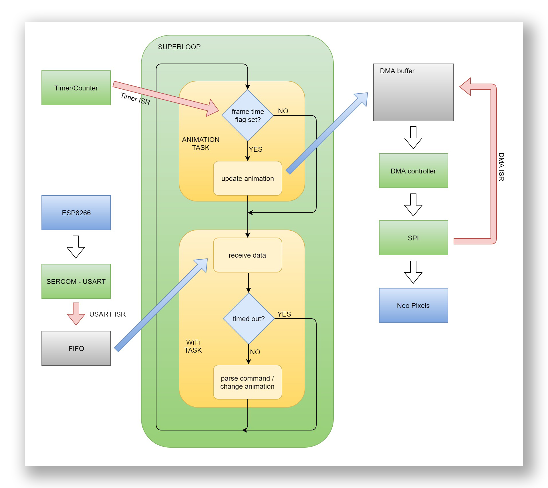
figure 4: the superloop (infinite loop) inside main(): in yellow the two tasks, the arrows indicates ISRs (red) and application calls (blue)
The key aspect of this simple strategy is that the two tasks never block: the NeoPixel_update_animation() task only draws a new frame to the framebuffer if the timer has overflown and set the flag, otherwise it returns immediately. Same for the WiFi_receive_data() function, which use a non blocking implementation of the serial function Serial_find_timeout(): this function looks for a matching string in the USART receive FIFO and returns if it fails after a number of attempts (or if the FIFO is empty). The DMA capability of the SAMD21, with a careful use of non blocking functions and ISRs allow to execute the two tasks “concurrently” in a simple single threaded environment.
The final test
I assembled a little test device with a NeoPixel ring and a SAMD21 micro breakout board from Sparkfun. I added a microphone connected to the ADC of the microcontroller and a new animation pattern that follows the level of incoming sounds/voices. I use a UDP client on my PC to change the patterns. The complete code is provided after the video.